
Patent for strong light reflector
2025-04-13
1、 Scenario description
High beams are used to make the line of sight farther away, or to increase visual clarity. But when driving at night, the high beam can make the oncoming driver visually produce instantaneous blindness, the blinding time is according to the driver's own vision, the surrounding environment is different for different durations, but the fastest time also lasts about 2 seconds, in these two seconds, the driver is like driving with his eyes closed, and the ability to observe the pedestrians around and the oncoming cars before and after is greatly reduced. When the rear vehicle turns on the high beams, there will be a large area of halo in the three rearview mirrors inside and outside the front car, and the three halos in front will narrow the visual range of the road conditions in front of the driver. According to the domestic police car accident data survey, the night accidents caused by the high beam account for 30%-40%, which shows the damage caused by the high beam in traffic, and most of the scientific research and development of the phenomenon of car accidents caused by the high beam in China is more inclined to solve the high beam itself, and replace the manual control high beam with a more intelligent high beam, and rarely go deep in the high beam reflection or warning driver. The patent relates to a passive reflection optical mechanical system for warning strong light irradiators, which is mainly used in the field of transportation. At present, most of the commonly used reflective traffic indicators are folded transparent particle surfaces, such as road signs, bicycle tail lights, curve warning posts, etc. Although the catadiopter transparent particles are more striking than full diffuse reflection, they are not obvious enough to warn the illuminated manipulator in some cases. The patent designs a right-angle secondary total reflection optical path, which can reflect as much incident light as possible near the light source, combined with non-rigid connection: realize the original return of the horizontal plane of the geometric optical path, and swing in a certain angle range in the vertical plane; Or return and swing at 90° to each other. Let the light source override see the strong sparkle reflection to play a strong warning role.
In addition to being used in automobiles, this product can also be fixed on other motorized bodies, bicycle bodies, ramp junction signs, road maintenance signs, warning triangle frames, etc., to enhance warnings and instructions. At the same time, in view of the dazzling situation of the oncoming vehicle light, the product can be installed in front of the above-mentioned device, and the driver of the light source vehicle is prompted to adjust the light in time. It is also possible to consider the application scenario in the design stage, and the passive reflective optical machine structure is shipped with it.

Specific instructions: the rear vehicle turns on the high beam, irradiates to the rear end of the vehicle in front, and the device installed at the rear of the car at this time reflects the incident light as much as possible to the original road to the driver of the light source vehicle, and at the same time because the device is equipped with a swing system, it will also be accompanied by a shining reflection effect, and the driver of the light source vehicle will get the warning that "the high beam has affected others", so as to adjust the lighting system according to the road conditions.
2、 Optical path design
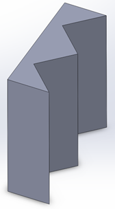
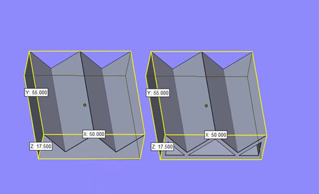
The optically reflective part consists of a sturdy plastic frame that measures the size of half a mobile phone, with a height of 55mm, a width of 50mm, and a thickness of 17.5mm. On the front of the frame, two coated right-angle mirrors are mounted, which constitute the reflective surface. These mirrors are precisely tuned and fixed to accurately reflect strong light signals.
The back of the mirror is designed to attach the mechanical rocking part to enable a small adjustment of the reflection angle. In actual installation, multiple strong light mirrors can be combined to form a larger reflective surface to meet the needs of the strong light signal, and the above is only a part of the reflective surface.
This design ensures that the strong light mirror has a stable structure and precise reflection function, and is suitable for applications that require high-intensity optical signal transmission. At the same time, the sturdiness and compact dimensions of the frame allow the reflective components to be flexibly installed and arranged in confined spaces.
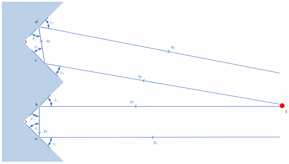
The reflective surfaces a, b, c, and d are successively 90° to each other, wherein a and b form a pair of mirror groups; c and d form a pair of mirrors. When the light source S emits rays p1 and q1, p1 is incident on the ab mirror group, and q1 is incident on the cd mirror group. After reflection, P1 and Q1 form the primary reflected rays of P2 and Q2, and the secondary reflected rays of P3 and Q3, respectively.
In this optical system, we define the angle α1 as the angle of incidence between P1 and the B mirror, β1 as the reflection angle between P2 and the B mirror, θ1 as the incident angle between P2 and the A mirror, and γ1 as the reflection angle between P3 and the A mirror. The angle α2 is the angle of incidence between Q1 and the C mirror, β2 is the reflection angle between Q2 and the C mirror, θ2 is the angle of incidence between Q2 and the D mirror, and γ2 is the reflection angle between Q3 and the D mirror.
According to the law of reflection of light, we can get α1=β1, θ1=γ1, α2=β2, θ2=γ2. Since a⊥b, c, ⊥d, the reflected lights p2 and q2 are parallel to the incident lights p1 and q1. When the ABCD side length is short enough, it can be approximated that the ray returns in the original way, i.e., P3 and Q3 are parallel to P1 and Q1. By precisely controlling the angle of incidence and reflection, so that the light can be reflected multiple times inside the system, we can achieve precise guidance and manipulation of the light, so as to achieve the precise transmission and control of the optical signal.
3、 Mechanical structure design
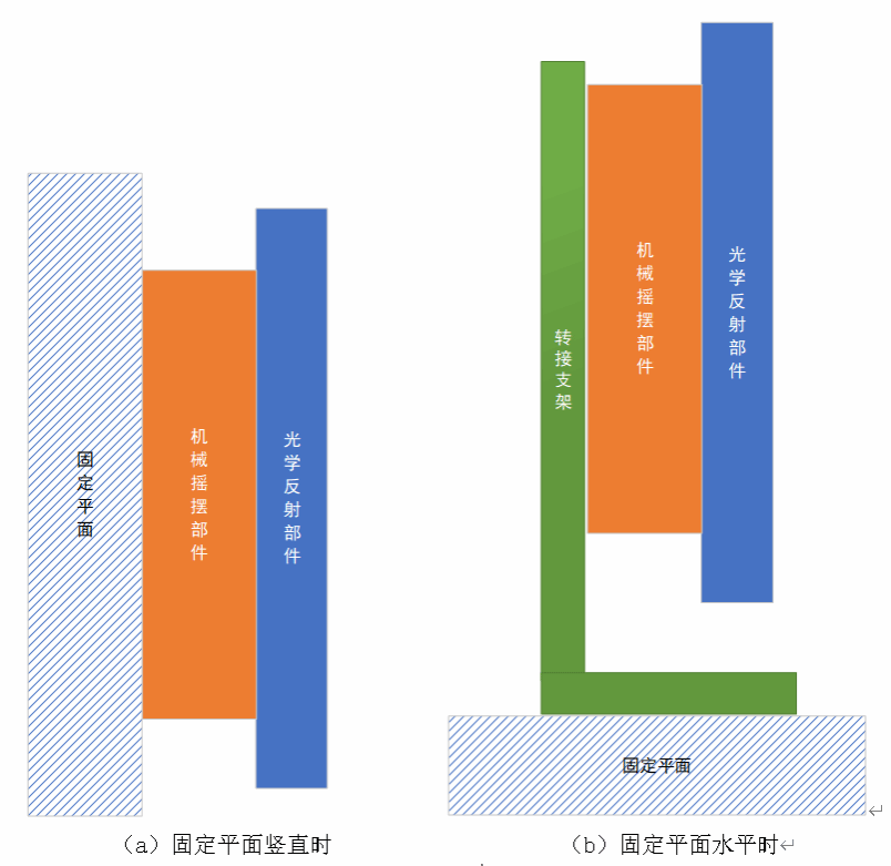
When the fixed plane is upright or horizontal, the device mainly swings backwards, which can directly adhere to the surface of the car body. The mechanical rocking parts are glued to the inner surface behind the housing and held together with the optical reflective parts by wire. For mechanical rocking parts, the vibration of the car makes the rocking parts oscillate in the up and down directions, and under the constraints of the elastic material, the mirror body oscillates about 3°, so as to reflect more light.
When the fixed plane is not completely upright or horizontal, e.g. when the device is mounted on a luggage rack, the device is required to swing mainly forward. This can also be done by adjusting the shape of the mechanical rocking part (inclination) or the angle of the adapter bracket. The oscillating function of the mechanical rocking part is the same as in the above case. In the case of the adapter bracket, it is connected to the mechanical rocking part in a paste-on connection, which can be designed to oscillate on its own, or its mounting method can be changed to adjust the angle of the mirror reflector.
In the above two cases, the range of variation of the exit and incident light is twice the range of the pitch angle of the mechanical rocking part.